关于美标插座的一些指标
网友问哪有美标电源插座夹持力参数。。
看看这里吧
Receptacles
Fed. Spec. Test:
Ground Pin Retention Test – The grounding contact of the receptacle is conditioned by twenty insertions with a 0.204 inch over-sized diameter pin. After conditioning, a 0.184 inch diameter pin is inserted in the grounding contact must be capable of supporting a weight of at least 4 ounces for one minute.
Fed. Spec. Test:
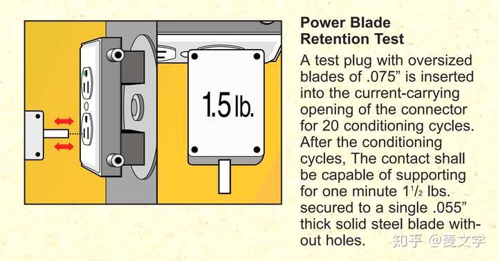
Power Blade Retention Test – A test plug with a single over-sized blade measuring 0.075 inch thick is inserted into each current carrying contact for twenty conditioning cycles. When the conditioning cycles are completed, each contact must be capable of supporting, for one minute, 1.5 pounds secured to a single 0.055 inch thick solid steel blade without holes.
Fed. Spec. Test:
Assembly Security Test – A force of 100 pounds is applied through the slots of the receptacle into the base while the bridge is supported at its screw mounting positions. Each receptacle is then examined for damage.
UL 498, Attachment Plugs and Receptacles, is the UL document that governs the performance requirements for receptacles and attachment plugs.
CSA C22.2, General use receptacles, attachment plugs, and similar wiring devices, is the Canadian standards document that governs the performance requirements for receptacles and attachment plugs and similar wiring devices for use in Canada.
Federal Specification WC596, General Specification for Connector, Electrical, Power. This document includes additional MIL Spec references and testing requirements.
National Electrical Code(NEC), or NFPA 70defines a receptacle as a “contact device installed at the outlet for the connection of an attachment plug. A single receptacle is a single contact device with no other contact device on the same yoke. A multiple receptacle is two or more contact devices on the same yoke.”
======================================================
Retention of blades: After ten insertions, not to exceed 40 lb of force, of a standard steel blade plug gauge, the receptacle must be able to hold (retain) a polished steel 2 bladed plug gauge without holes (the grounding blade removed) against a 3 lb force for 1 minute. The receptacle must release a polished steel 3 bladed plug gauge with holes at no more than 15 lb of force.
Current overload: To pass this test, the same test samples from the previous test are utilized and must not exhibit any electrical or mechanical failure, pitting or burning of the contacts, that would affect the intended function. The test sample device is subjected to 100 insertions & removals of a mating plug making and breaking dc current through a resistive load at 150% of device rating. The blade of the attachment plug is to mate with the contact of the receptacle for not more than 1 second during each cycle.
Temperature rise: After the previous current overload test, the same samples are subjected to this temperature rise test. Strategically placed thermocouples help to ensure the test subject passes this test which requires that the contact temperature rise of a flush or self-contained receptacle shall not be more than 30°C (54°F) when the receptacle is carrying its maximum rated current.
Repeat blade retention: For those test samples experiencing the previous temperature rise test, they must additionally pass the Blade Retention test described in item 1 above.
Resistance to arcing: The outlets that were subjected to the 100 cycles of operation in the Overload Test described in item 2 above must perform acceptably when subjected to an additional 150 cycles of operation under the overload test conditions following the temperature test and the repeated retention of blades test. There is also a dielectric test built into this test; 1500 volts for 1 minute to ensure the integrity of the device.I think it is worth stopping here for a moment to reflect on this specific test as it is a good example of a redundancy that is not unique in this specific UL standard. In this case, the test samples used are not new or fresh out of the box. These samples have experienced an overload test as well as the temperature and repeated retention of blades tests. We’ll see more of this redundancy as we move into the Hospital Grade and other similar products. First, let’s continue looking at what a receptacle must endure as part of this UL standard performance test requirements.
Terminal strength: The standard 3-prong steel test gauge is inserted 10 times and the maximum insertion force should not exceed 40 lbf. If the receptacle has a break-off tab, it is removed prior to the conditioning. After conditioning, each terminal is wired with 12 AWG solid copper wire by applying 14 in-lbs of tightening torque. The wire is stripped to the length specified in the manufacturer’s installation instructions. Wire-binding screw terminals are wired by placing the stripped conductor under the screw head and wrapping it ⅔–¾ turn around the screw. Pressure-wire terminals are wired by inserting the stripped conductor into the terminal. The terminal screw is then torqued, loosened and re-torqued. Following the last torquing, each terminal is to be subjected to a straight 20-lbf (89-N) pull applied to each wire for 1 minute perpendicular to the plane of the back cover of the receptacle; the wire shall remain in place. Following this pull, the receptacle must be able to hold (retain) a polished steel 2 bladed plug gauge (without holes in the blades and without ground) against a 3 lb force for 1 minute. The receptacle must release a polished steel 3 bladed plug gauge (with holes in the blades) at no more than 15 lb of force.
Grounding pin retention: In these tests, the grounding pin is the focus. It is subjected to various situations including a weight of 5 lbs located 6 inches from the outlet face, a 360 degree rotation of a grounding pin during which time the continuity must be maintained. After the receptacle is subjected to these tests, the ground contact must retain a pin being subjected to a 4 oz. and 2 oz. weight depending upon the dimension of the pin.
Fault current: For this test, the receptacle is subjected to a through fault current of 1,000 amperes downstream of a 15-A or 20-A circuit breaker. After the receptacle experiences this fault current, it must retain its integrity as demonstrated by a continuity check after removing and reinserting the attachment plug.
Dielectric voltage withstand: For tamper-resistant receptacles, a dielectric test is performed to determine the effectiveness of a device’s insulation. In this case, a potential equal to twice the rated voltage of the receptacle plus 1,000 volts is applied between live parts of opposite polarity and between live parts and grounded or dead metal parts and must not exhibit any arcing or breakdown.
Mold stress relief: Unwired receptacles are subjected to 70oC for 7 hours and after being allowed to cool, measurements are made where there shall not be any warping, shrinkage or other distortion that results in the device not performing as expected.
Dielectric voltage withstand (repeated): After the above mold stress relief test, the same test specimens are again subjected to the dielectric voltage withstand tests described above in item 9.
Assembly security: This test is quite grueling in that the subject receptacle must endure a 50 lb force through extra-long blades inserted into the receptacle and directly on the back of the receptacle.
